Experimenting With Magnetometer Calibration
16 Sep 2014Recently I’ve started volunteering with RoboSail, a program to get high school students interested in technology and programming. They needed some tilt compensated compass code, so I volunteered to work on that. Here’s what I found.
Background
A basic compass uses the magnetic field X and Y components to calculate the angle to north. Think of high school trigonometry and you’ll get it. The problem with this solution is when the compass is no longer level: the X and Y axes are now measuring some Z. What we really need to do is rotate it axes back to level. That’s where the accelerometer comes in.
The accelerometer makes a very good “down” measurement, at least when you’re sitting still. And it can do this in any orientation: if you’re tilted backwards the accelerometer could tell you your exact pitch angle. If you lean to the right the accelerometer could tell you that as well.
A tilt compensated compass uses acceleration to rotate the magnetic axes back to level.
There’s a great series of app notes on the subject here:
- Calibrating an eCompass in the Presence of Hard and Soft-Iron Interference
- Layout Recommendations for PCBs Using a Magnetometer Sensor
- Implementing a Tilt-Compensated eCompass using Accelerometer and Magnetometer Sensors
- Accuracy of Angle Estimation in eCompass and 3-D Pointer Applications
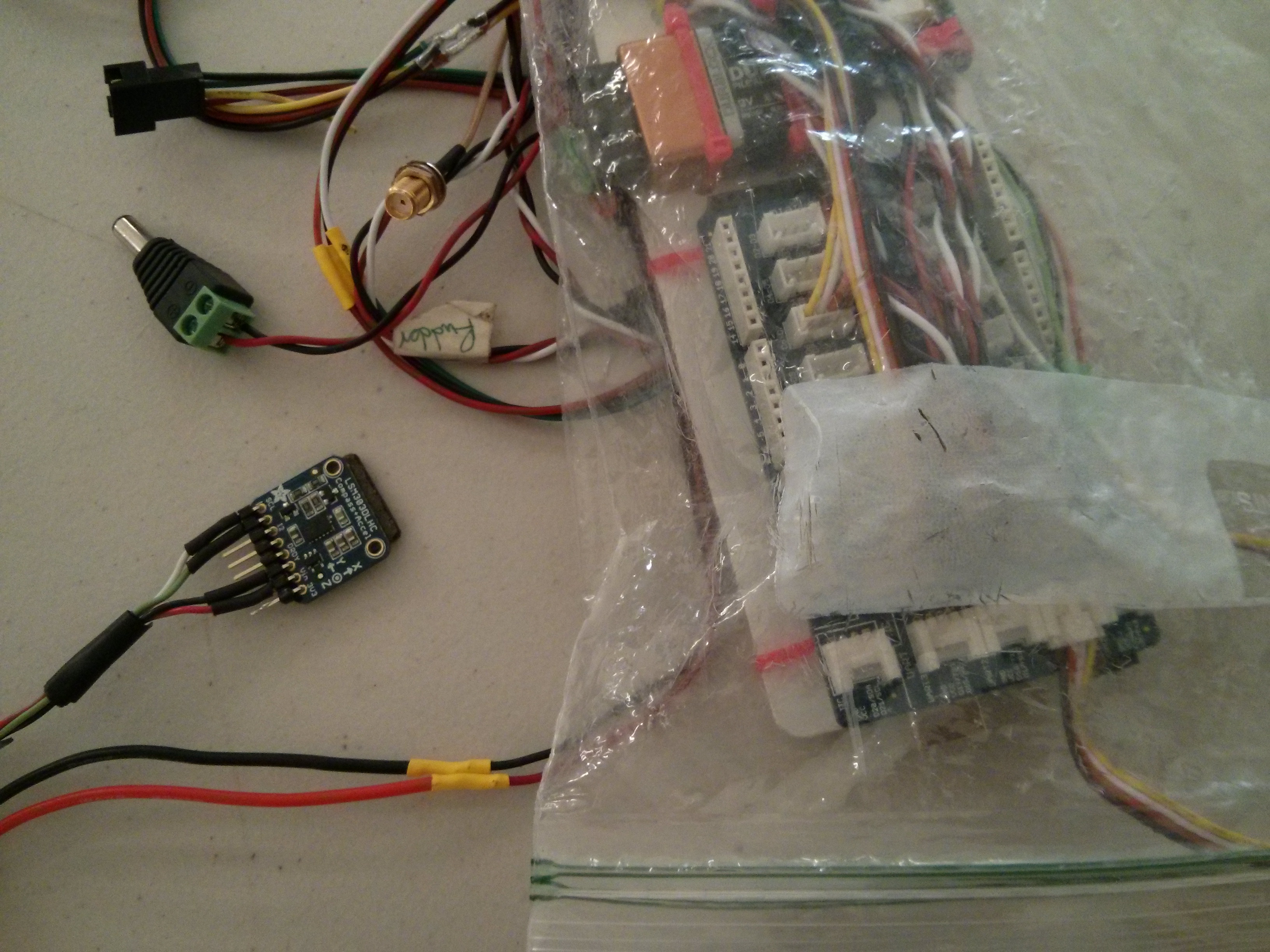
For this testing I’m using an Arduino hooked up to the LSM303DLHC breakout board from Adafruit (source). The LSM303DLHC is at the end of a long cord, and I did all my testing at my desk. The LSM303DLHC sat in front of my keyboard.
Calibration
Magnetometers need two different forms of calibration: hard iron and soft iron. The problem is described nicely in AN4246.
Magnetometers suffer from two problems: measurements are offset from 0,0,0 (called hard-iron), and rotating the magnetic field vector around (aka, spinning the sensor) doesn’t trace a perfect sphere like it should (soft-iron).
These problems are displayed in the following image. The blimp on the right is raw readings, uncorrected. The sphere on the left is corrected readings. The two calibrations are:
- hard-iron, to translate the blimp to the upper left
- soft-iron, to transform the blimp shape into a sphere shape
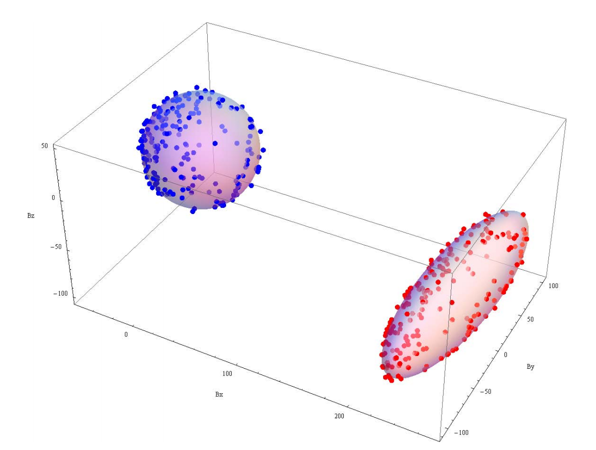 (image from page 11 of AN4246)
Hard-iron is caused by static magnetic fields near the sensor such as permanent magnets. Hard-iron is constant in any orientation. Soft-iron is caused by earth’s magnetic field being redirected by ferrous material near the sensor, and changes for different orientations.
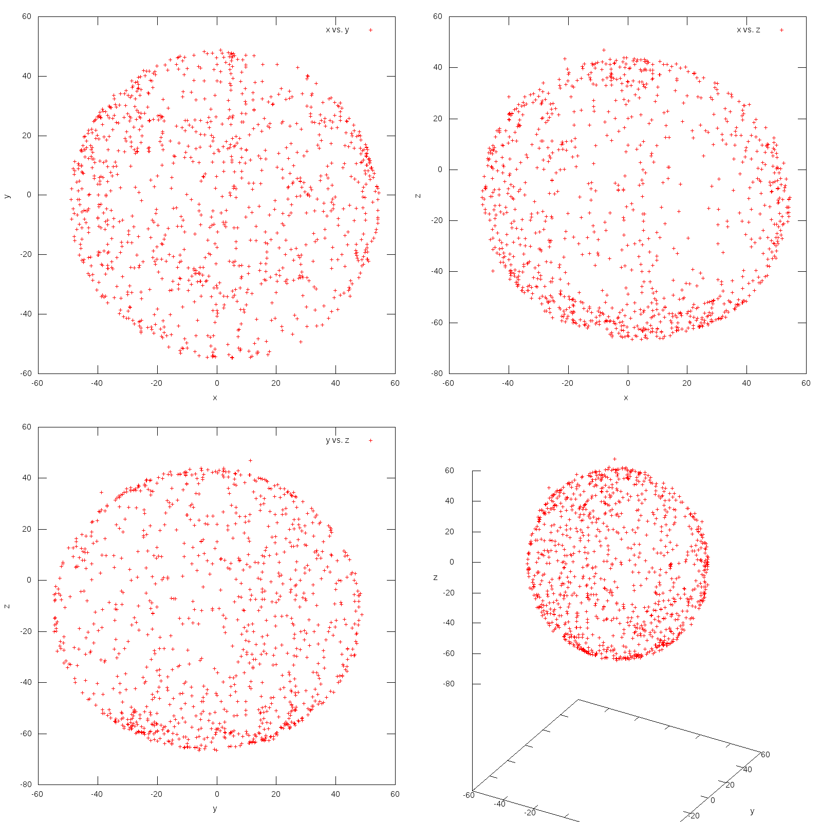
In order to evaluate the effect of hard and soft iron interference I took two identical setups and plotted their points. Here’s the resulting graphs that I got:
Unit SRLM
Unit Boat
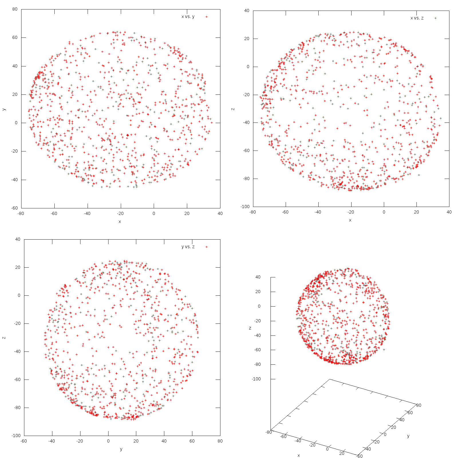
It’s immediately apparent that, for this setup, soft-iron is negligible. The results are nearly spherical straight from the sensor. Hard-iron, however, is a dominating factor. Unit SRLM has an offset of roughly 2,-4,-15 and Unit Boat has an offset of roughly -22,10,-30.
The navigation equations are very sensitive to accurate hard-iron settings. If they’re off at all then the results tend to “lock up” and not move much. In hind sight this is clear, since the magn vector is dominated by the hard-iron offset, which prevents sensor rotation from changing it’s orientation relative to origin.
The code
Overall, the code is fairly straight forward. You can copy it directly from AN4248. I’ve posted all of the code into a gist.
The most interesting bit of code is the actual conversion, which is here:
// Freescale solution
roll = atan2(accl_y, accl_z);
pitch = atan(-accl_x / (accl_y * sin(roll) + accl_z * cos(roll)));

float magn_fy_fs = magn_z * sin(roll) - magn_y*cos(roll);
float magn_fx_fs = magn_x * cos(pitch) + magn_y * sin(pitch) * sin(roll) + magn_z * sin(pitch) * cos(roll);

yaw = atan2(magn_fy_fs, magn_fx_fs);

roll = roll * RAD_CONV;
pitch = pitch * RAD_CONV;
yaw = yaw * RAD_CONV;
As you can see this is directly from the Freescale app note. The only difference is the absence of hardiron calibration, which I moved to after we take the measurements:
// Get a new sensor event
sensors_event_t event_accl;
sensors_event_t event_magn;

accl->getEvent(&event_accl);
magn->getEvent(&event_magn);

// Signs choosen so that, when axis is down, the value is + 1g
float accl_x = -event_accl.acceleration.x;
float accl_y = event_accl.acceleration.y;
float accl_z = event_accl.acceleration.z;

// Signs should be choosen so that, when the axis is down, the value is + positive.
// But that doesn't seem to work ?...
float magn_x = event_magn.magnetic.x - hardiron_x;
float magn_y = -event_magn.magnetic.y - hardiron_y;
float magn_z = -event_magn.magnetic.z - hardiron_z;
The only curious thing in here is the signs: I negate accl_x, magn_y, and magn_z. Why? Because that’s what seemed to be needed in order to make the coordinates line up with a standard North-East-Down reference frame:
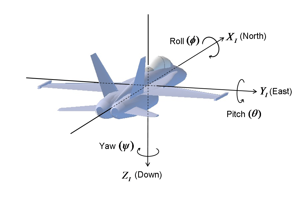 Image courtesy of http://www.chrobotics.com/
Conclusion
Hard-iron calibration is critical. Without accurate values the resulting heading is completely unusable. Once that’s correct, then implementing the algorithm is just a matter of getting the correct axis directions.